a few notes on my field-box raspi with digiview
When the DJI digital FPV goggles came out they changed the (FPV) world - we wen't from static ridden, low resolution analogue pictures to crisp HD image - and personally it didn't take me very long to not want to fly analog anymore.
But with that change, there was also something important missing - a way for people to spectate - sure you can bring a second set of 700 euro goggles - or that overpriced radio of DJI's (that you can use to pull video to hdmi, but can't use to actually fly.. lol) but, well those options aren't really great.
After a while the folks from the FPV Out Club managed to reverse engineer the way DJI is doing the video signal through usb-c, and thus brought easy ways to spectate & stream to the community.
By now you have options to run this from Android, from a SBC (Raspberry PI) or even from a compatible browser.
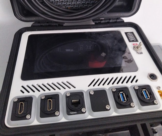
When the first version of the DigiView SBC solution came out I got inspired to build myself a field-box with a raspberry Pi & a screen with a rugged looking case, running that software.
My goals were:
- have a pelikan like case (cheap china clone)
- give it a bit more "serious" and less "consumer" look
- break out most of the input/output of the raspberry PI so they can be used in the field
- have a battery inside
- have the option to charge / supply power from the outside, a typical flight battery if necessary
Whenever I show photos of the box, one of the main questions I'm being asked is about what components I've build in to make the whole power / battery thing work - I'm trying to de-mystify that here.
Don't blindly follow what I'm writing!
I'm not an electrical engineer - I've researched what I've build to the best of my abilities, but the kind of batteries we use in the hobby aren't safe to start with, and while I'm confident in my work, there is always the chance that I have missed something or that I have screwed up.
Even if I haven't, if you follow blindly, you might.
Given the kind of batteries, and the inherent fire risk, I urge you to great caution, and remember someting some random dude writes on the internet is not always a reliable source of information. If you burn down your house, or seriously harm someone following what I did, that's on you - I won't take any responsibility.
Make sure you understand what you are doing.
There are easier, thus better ways to achieve similar function!
There is multiple ways on how you can achieve similar results, that are easier than my solution:
- don't have an internal battery, power through USB - well, essentially the easiest version, all you need is a usb port and a cable to the raspberry pi, in the field you power from a powerbank.
- don't have an internal battery, power from other plugs - if you want to power from for example your flight battery, an xt60-m outlet & an appropriate sized step down converter (to 5V) will do the trick
- have internal battery, but use a ready available usb-charger board, there is 1S and 2S boards with builtin power converters and everything ready available, if you are ok charging through USB and you don't want to use external power in the field this is the better solution
Known Issues
The solution I'm showing here has a set of issues that are based in its design / the components I've picked. Some of these are choices, others are part of my own learning process.
This does not have a proper charging circuit.
- The BMS + the step down converter with current limiter do charge the batteries, but this is by far not the ideal way of doing things, as charging this way does not follow the ideal charging curve.
- The BMS I'm using does not balance the cells! It will cut off charging / discharging when the first of the two cells hits the limit, this means over time it won't use the batteries to full capacity (getting the batteries out and using a proper charger solves that).
- because of the step down converter used for the power input, and the lack of a balancing port, you can't just use your external charger to improve on previously mentioned issue. You can use it as a power supply.
- the battery charge indicator will show full charge during charging, as it shows the voltage from the power supply during charge
- it doesn't seemlessly switch between external power supply and internal batteries, as there is a switch delay, which means the rasberry pi will turn off / reboot
lets get started....
If you made it past all the disclaimer boxes, you hopefully understand by now that this is a not a how-to recipe to follow, but more information that you should use as a starting point. From here on out I'm going to cut down the warnings, and will simply assume you know what you are doing - if at any point you have doubts because you are unsure, please check for further material.
If you don't know whats meant when I say "appropriate voltage" or "appropriate C rating" instead of giving a number, then this is not for you.
The components used here are no recommendations, there is a good chance there is better ones out there, and some are so generic that there is equivalents from other vendors that will just work as fine.
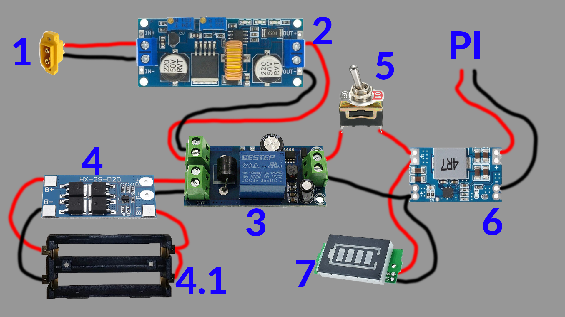
... at 1, the external power supply
to use an external power supply you want a socket that you can plugin to - in the image above I'm simply showing a XT60-m socket, which is a quite common connector to be used in the FPV hobby. In my own box I have one of these, and in parallel a barrel plug - obviously they should never have both plugged in, but that gives me the option to power from a battery in the field, and charge from a power brick at home.
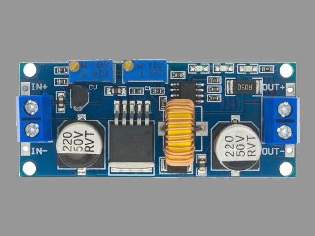
2 is the first real component, a step-down converter with current limiter
I'm using a DC-DC Adjustable Step-down Buck Converter XL4015 5A - with Current Limiter. With its range from 8 to 36V input, it allows me to use my typical flight batteries from 3S to 6S as power supply (input) no problem (and has a bit room upward), while the current limiter allows me to limit the current that goes to my internal battery pack, which is important to keep below the safe c-rating of the internal Li-Ion cells.
the output voltage and current are adjusted through the two potentiometers at the top, there is also 3 led's that show when the module is in CC, CV or cut off.
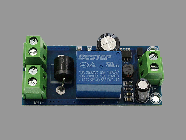
3 switches between battery and power supply
This is a module sold as YX850 Power Failure Automatic Switch Backup Battery Lithium Battery Module 5V-48V Universal Emergency Converter Module Board (gotta love the SEO optimized names..). Essentially this is a relay thats fed from a step-down converter which itself takes power from the power supply - if it is powered the relay will switch the power supplies positive line to the load, if the power from the power supply sinks below 5V the relay will default back to the batteries positive line. There is various modules like this out there - essential for this use case is that its one that has a diode allowing a charging current to go to the battery while the relay is set to power supply (note: diode will lower voltage, power supply needs to be adjusted)
good video explaining how the module works
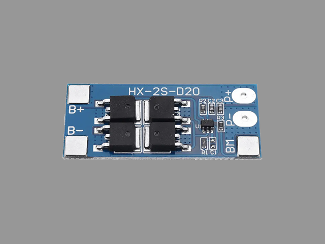
4 is the battery protection board...
the HX-2S-D20 is a limited BMS which protects the battery from overcharging, from discharging too much, and has short circuit protection (allthough, I haven't tested the later one). Here its main use is to cut the batteries off once they are full and to cut them off if they get too empty. This one isn't balancing.
here is a youtube video that explains a bit more on how these kind of BMS work (different model though)
4.1 is a battery holder
really, its that simple, its a keystone-1048, and there is nothing complicated about it - I just figured the name might be helpful.
5 is another trivial component: a switch
Its a switch. No magic about it. The placement makes sure it connects/disconnects the actual load, including the led from the battery capacity indicator, making sure neither the following step down converter nor that led consume delicious battery voltage when flipped off.

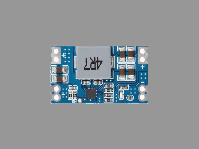
6 is another step down converter!
This one steps down from the 2S battery voltage (or the stepped-down power supply) to 5V, which is the voltage needed for the Raspberry Pi. There is a plentitude of alternatives available for this one.
You will notice that (7) is connected to the inputs here.
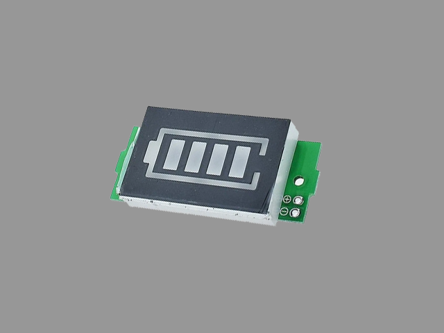
7 is the battery capacity indicator
.. essentially a different looking volt-meter, and you can find plenty volt-meters in a similar form factor, I just liked the idea of having the stylized battery there - although in hind-sight a volt-meter would have a better information value.
I've been considering adding a voltage divider, so I could read the battery charge from the Raspberry PI as well, and display it on screen somehow, but I never got the drive to actually do it.
PI - the raspberry PI with screen
Not really included in the picture, the device thats actually being powered by all this - a RaspberryPi 4, powered through the power and gnd pins on the PI (could also just be a cable from step-down converter to one of the power inputs (usb, barrel plug..).
fin
I hope this is helpful, be careful when building, and if you find any mistakes, especially of the life-threatening sort, please contact me on Discord: PeterPower#0001, a server where you can find me is linked in the footer.